
Mini 5-axis CNC milling machine conceptual design
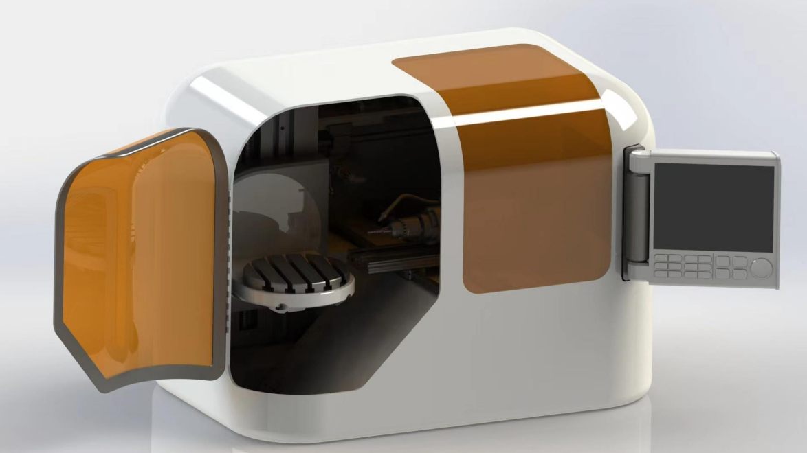
This project focuses on presenting a conceptual design of a compact, desktop-sized CNC milling machine. The project aims to provide an affordable, versatile solution for designers and engineers needing high-precision milling capabilities in a small, easy-to-use package.
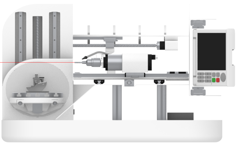
front view of the machine
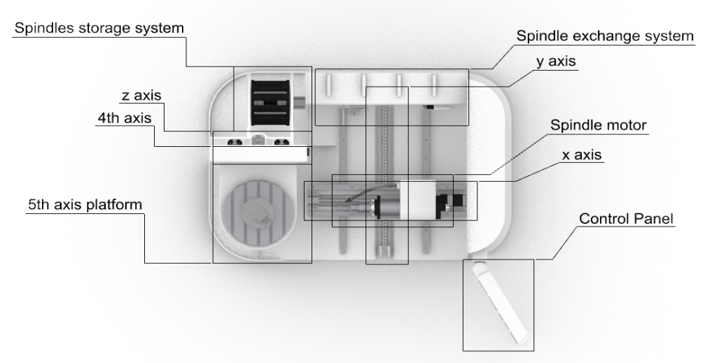
birdside view (x, y, z + 4th, 5th axis, 5 degree of freedom)
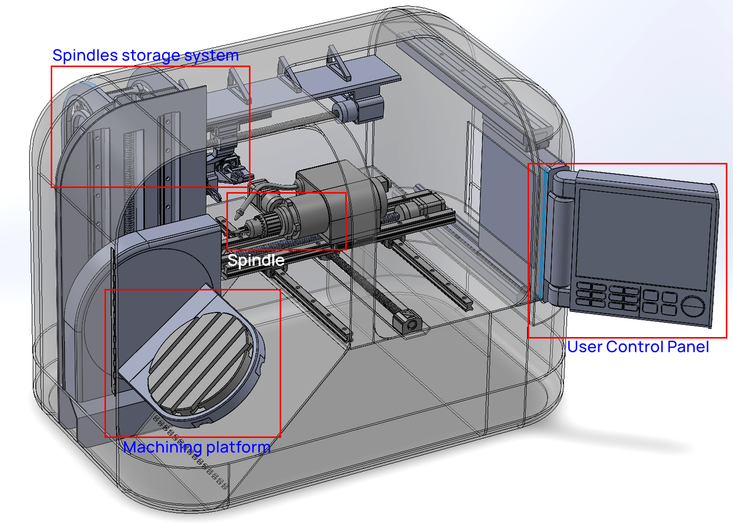
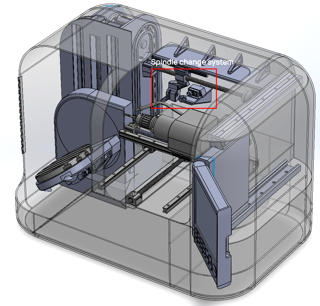
3D view of the machine
The CNC milling machine offers five degrees of freedom. The machining platform provides three adjustable axes (the z-axis for height adjustment, and the 4th and 5th axes are rotational axes). The tool-carrying platform provides adjustability in two axes (x-axis and y-axis for planar movement).
The machining platform is a circular tray. A motor drives the "central gear", which in turn drives four connected gears (two "middle gears" and two "gears on the far ends"). These outer gears are connected to two screw shafts, which control the platform's rotation through rollers embedded in the base of the platform, as shown in the diagram.
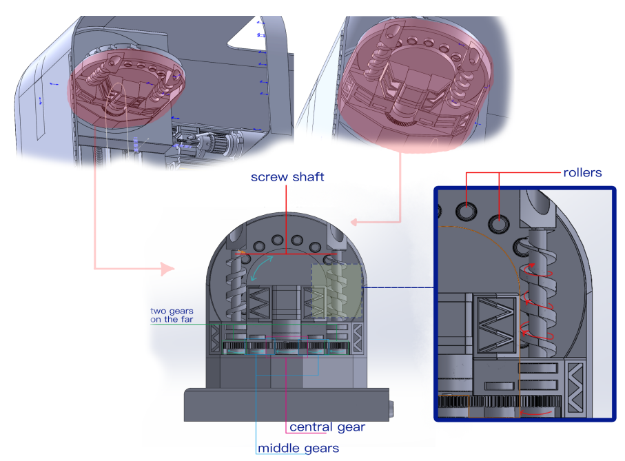
Machining platform mechanical structure
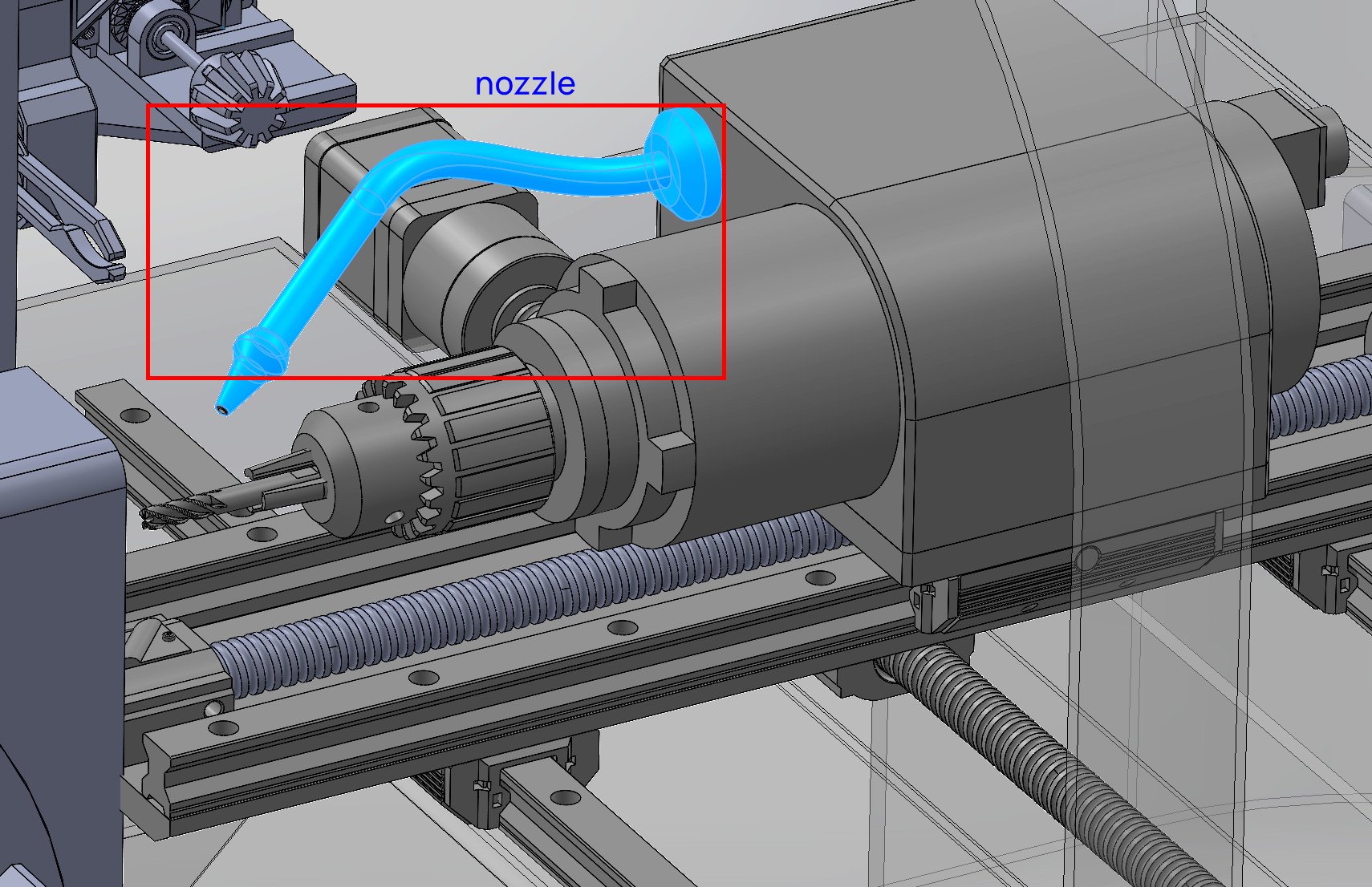
Close-up of the spindle and nozzle
Through the nozzle, the coolant sprayed onto the machining platform returns to the storage container through a gap at the bottom left due to gravity. The liquid in the storage container is then pumped back into the nozzle for reuse in a continuous cycle. The enclosed space next to the coolant pool is used to house peripheral electronic modules, such as microcontrollers.
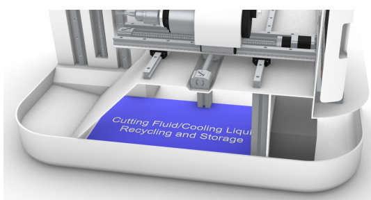
coolant storage space
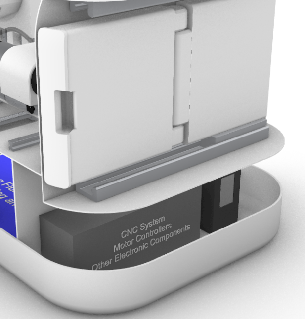
Peripherals space
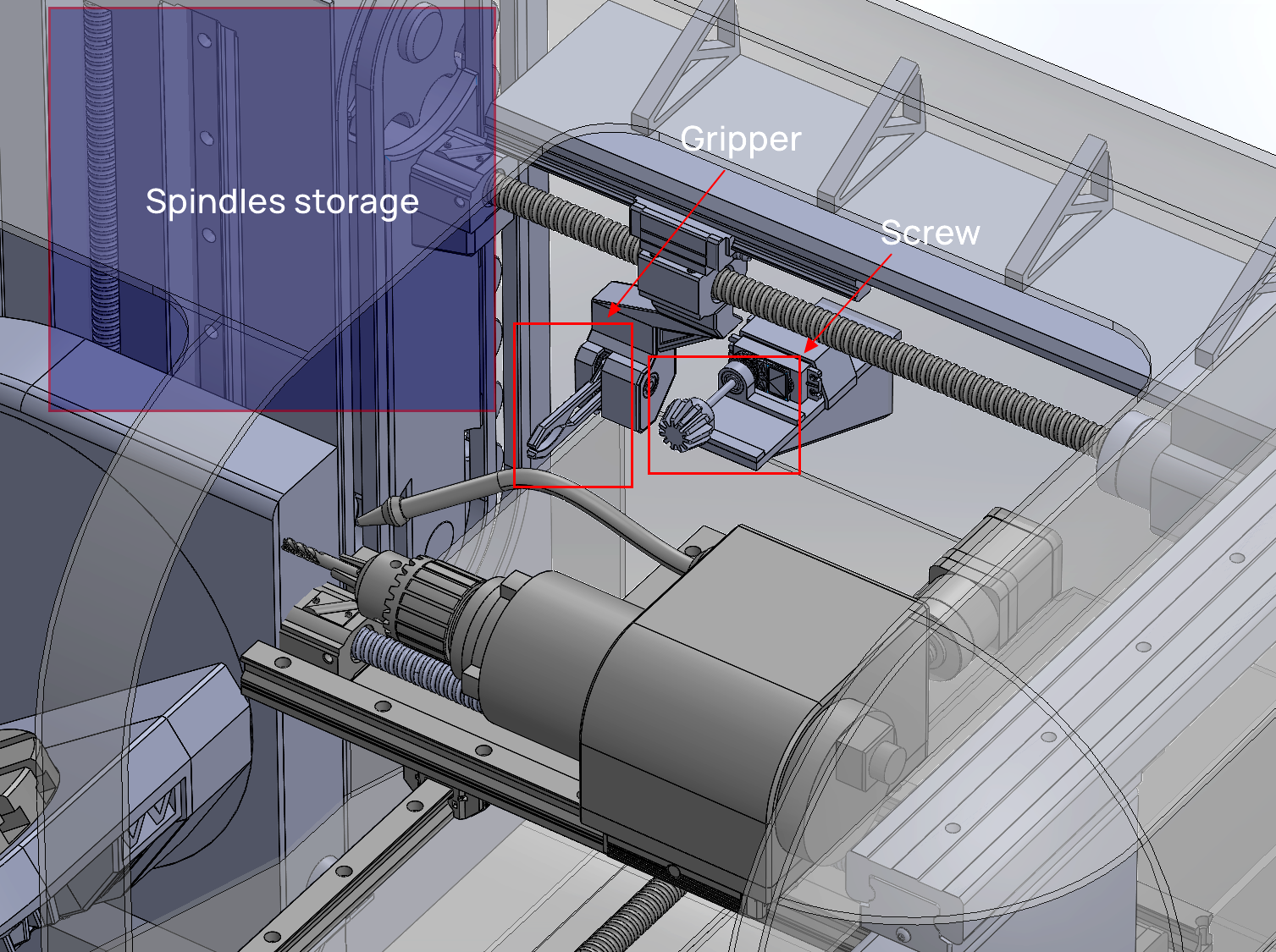
When machining complex parts, the spindle (cutting tool) may need to be changed frequently. Manual replacement is impractical as it is time-consuming and labor-intensive. To address this, I designed an automatic tool-changing system mounted on the back of the machine.
As shown in the diagram, when a tool change is required, the platform moves the currently loaded spindle to the back of the machine. Once aligned, the 'screw' first loosens the current tool, and then the 'gripper' grabs and removes the tool, placing it in the adjacent spindle storage.
The spindles are stored vertically within the storage system. A track-like mechanical structure controls the movement of various tools mounted on it. As shown in the diagram, the track rotates and delivers the tool to be replaced to the gripper. A new tool is then selected from the storage, aligned, and mounted on the machine, after which the 'screw' tightens it again.
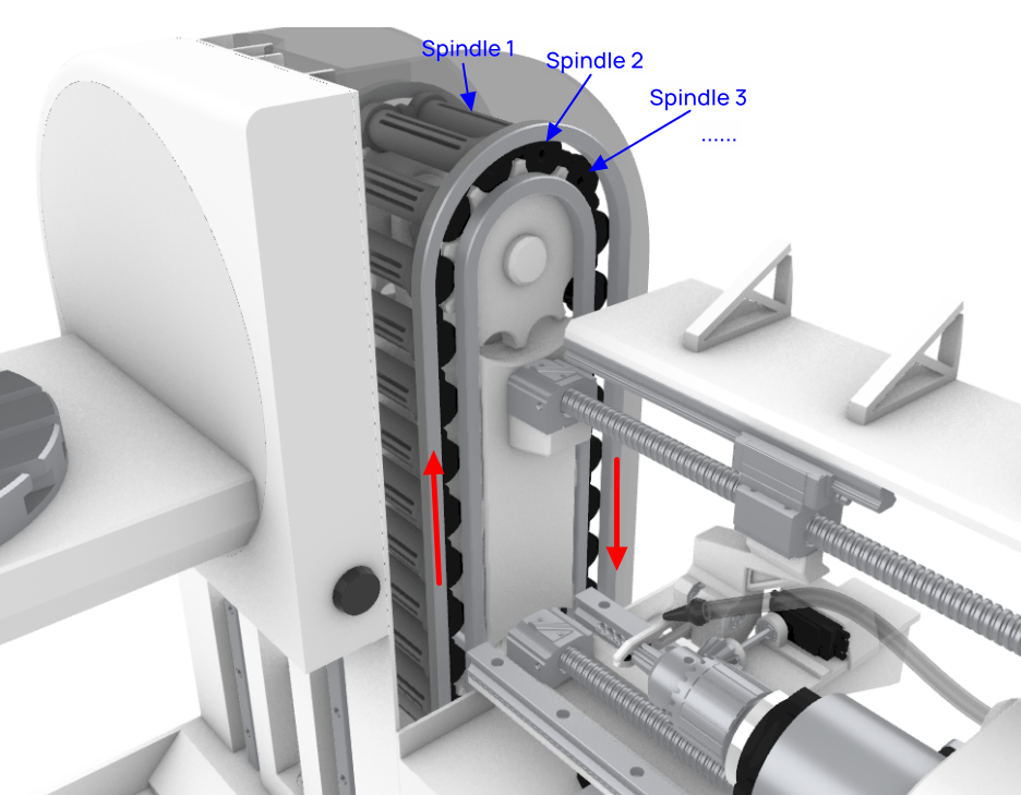
Spindles (cutting tool) replacement system
This project was completed during my second year at UofT, so the scope was limited to a conceptual design without any actual prototype or practical validation. We were not required to design the specific internal control systems, such as algorithms or hardware circuits.