Arduino Mega Shield V1.0 
A fully customized 4-layers PCB for mechatronics DIY hobbyist that can support up to 24 servo motors, bluetooth/2.4GHz transceiver, gyroscope, and camera module. (Up to 5.5V/15A input)

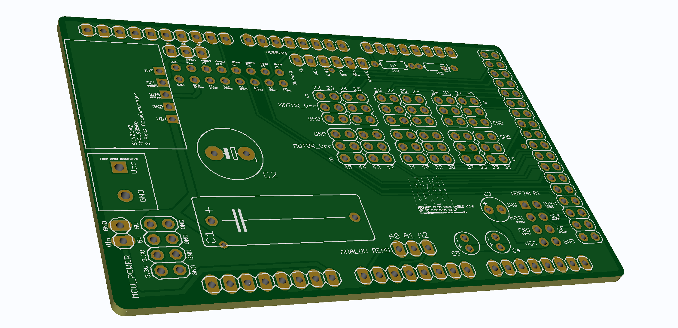
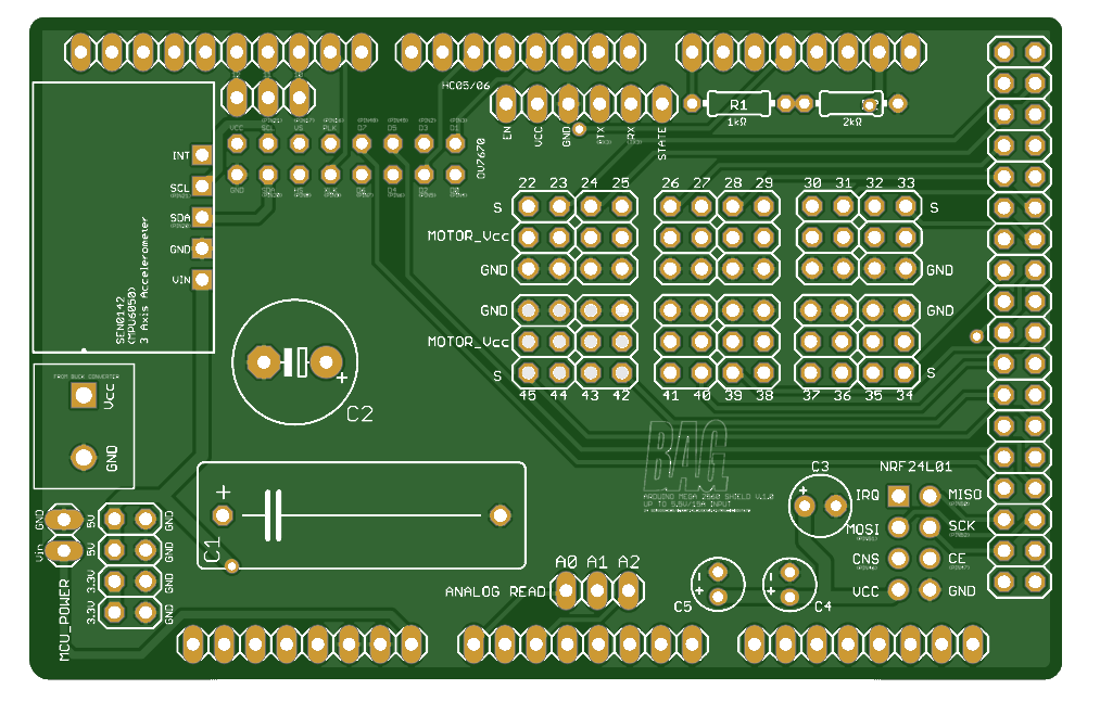
This PCB is an Arduino Mega shield designed primarily for driving servo motors, providing DIY enthusiasts with a comprehensive development shield. It greatly enhances development efficiency while allowing for easy and organized wiring of all peripheral components to the board. 

It features:

Pin Definition

To help users get started quickly, please refer to the following pin mapping for connections. Below are the shield pins corresponding to the pins on the Arduino Mega2560:

B.A.G Shield Pin Correspond Arduino Pin Description
HC05/HC06
EN - -
VCC - Main power supply (shared with servo motors)
GND GND -
TX RX3 -
RX TX3 -
STATE - -
Servo Motor​ Pins
S PIN 22~45 -
MOTOR_Vcc - Main power supply (shared with HC05/HC06)
GND GND -
NRF24L01
IRQ - -
MOSI PIN 51 -
CNS PIN 46 -
VCC 3.3V PIN MCU provides the power
MISO PIN 50 -
SCK PIN 52 -
CE PIN 47 -
GND GND -
MCU_POWER
VIN - MCU power supply (separate power supply from the main power supply)
GND GND -
SEN0142(MPU6050)
INT - -
SCL PIN 21 -
SDA PIN 20 -
GND GND -
VIN 5V PIN MCU provides the power
OV7670
VCC 3.3V PIN MCU provides the power
SCL PIN 21 -
VS PIN 17 -
PLK PIN 16 -
D7 PIN 48 -
D5 PIN 49 -
D3 PIN 2 -
D1 PIN 3 -
D0 PIN 4 -
D2 PIN 5 -
D4 PIN 6 -
D6 PIN 7 -
XLK PIN 9 -
HS PIN 8 -
SDA PIN 20 -
GND GND -
Other Pins
3.3V 3.3V PIN -
5V 5V PIN -
12 PIN 12 -
11 PIN 11 -
10 PIN 10 -
A0 (Analog Read) A0 PIN -
A1 (Analog Read) A1 PIN -
A2 (Analog Read) A2 PIN -
C1 (+) - Connect to the main power supply
C2​ (+) - Connect to the main power supply
C3 ​(+) 3.3V PIN -
C4​ (+) 3.3V PIN -
C5​ (+) 3.3V PIN -

Assembly Guidance

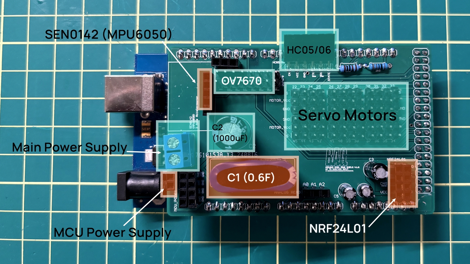
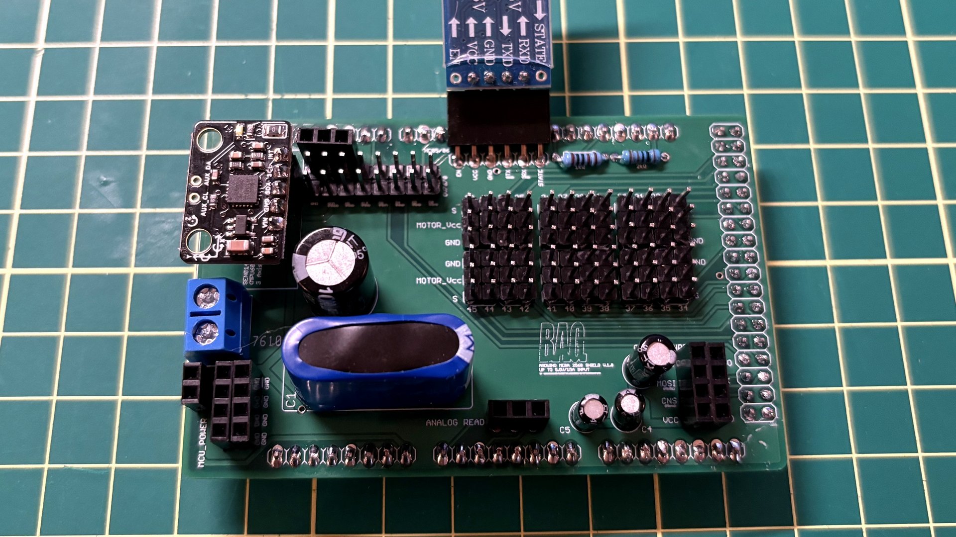
I've fabricated and assembled this PCB, using it in the Hexapod Robot project. 

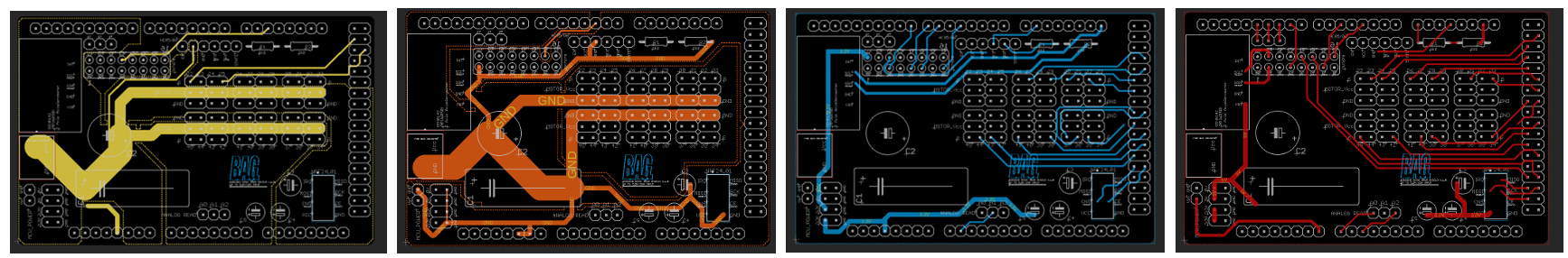
To power 18 RDS3225 servo motors simultaneously while avoiding voltage drop issues, a large 0.6F capacitor was placed at C1, with a relatively smaller 1000µF capacitor placed in parallel at C2. 

Capacitors of 100µF, 10µF, and 0.1µF were placed at C3, C4, and C5 respectively, to ensure the stability of power supply for all peripherals. A 1kΩ resistor was placed at R1 and a 2kΩ resistor at R2 to create a voltage divider circuit, which reduces the voltage to around 3.3V for the RX pin of the HC05/06 module. For more details, please refer to the shared Gerber file below.

https://drive.google.com/drive/folders/17j_bDiwszHmci_YNZK1wv7SDB-q9JGdj?usp=sharing