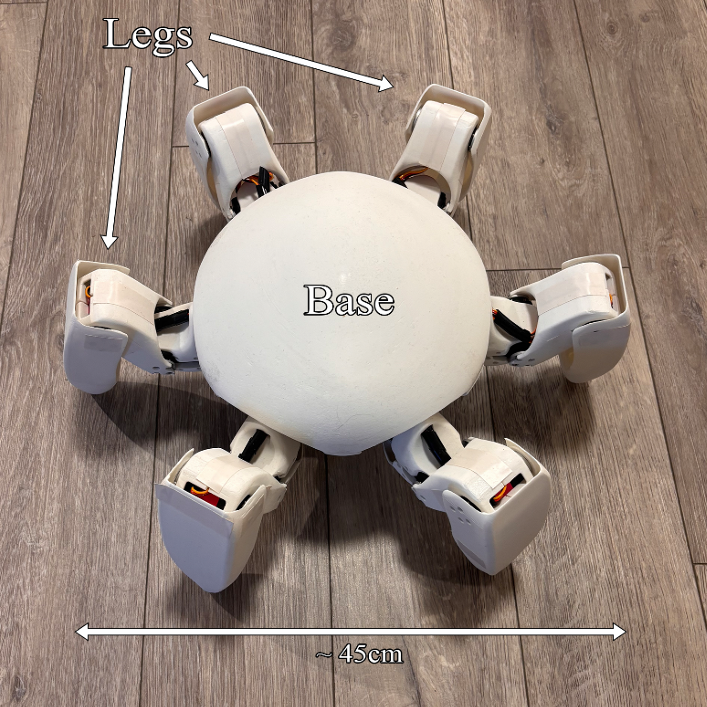
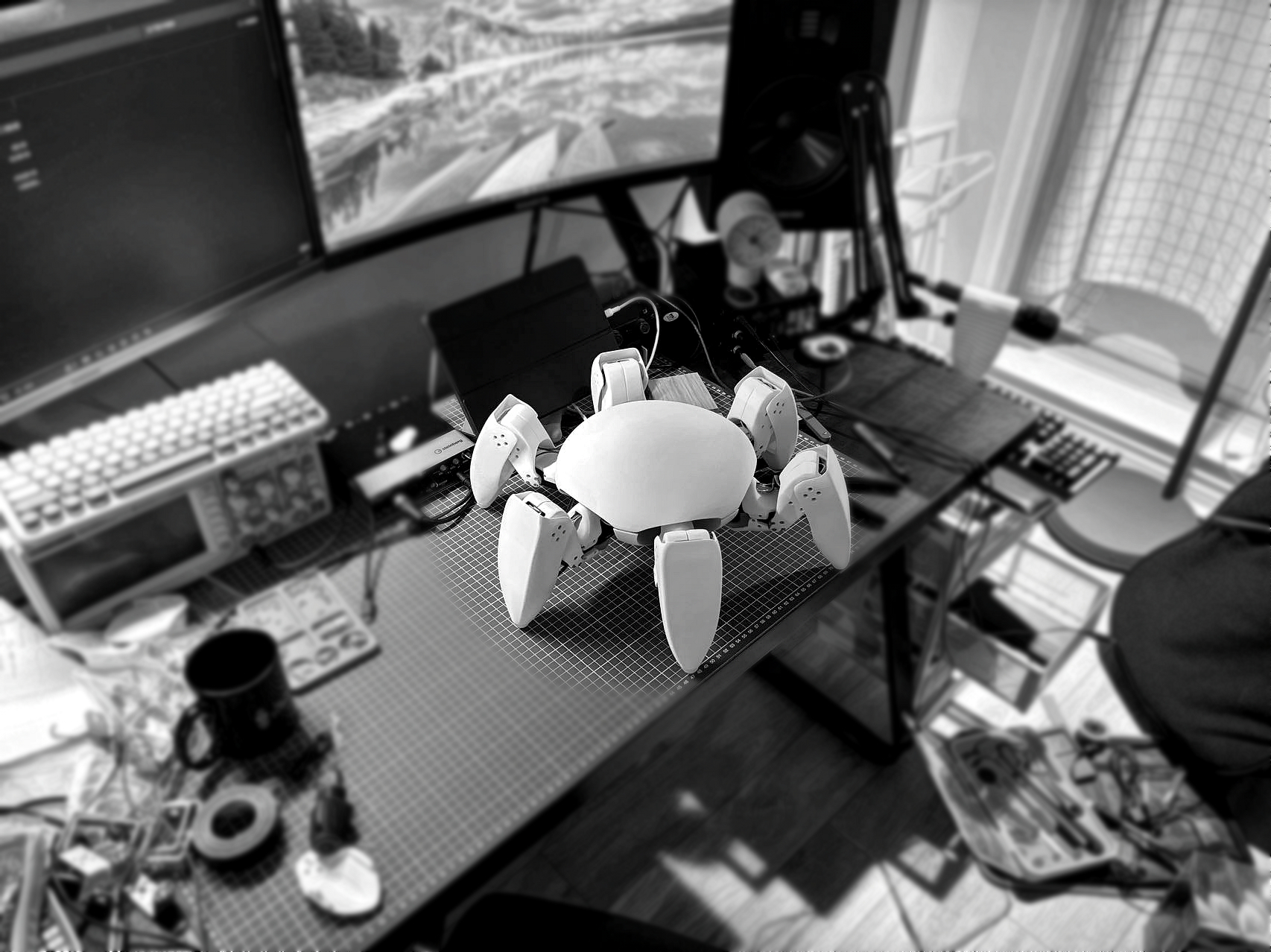
A six-legged robot named "Eclipse." The project started in early 2024 while I was doing my internship. I independently design, fabricate, simulate, and program the robot.
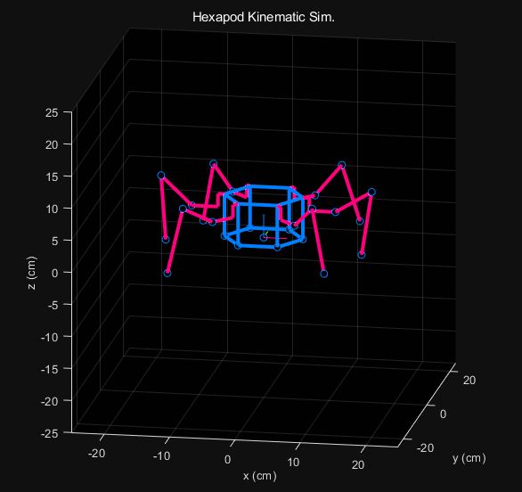
A kinematic simulation using a simplified "stick model" was conducted in MATLAB at the early stage.
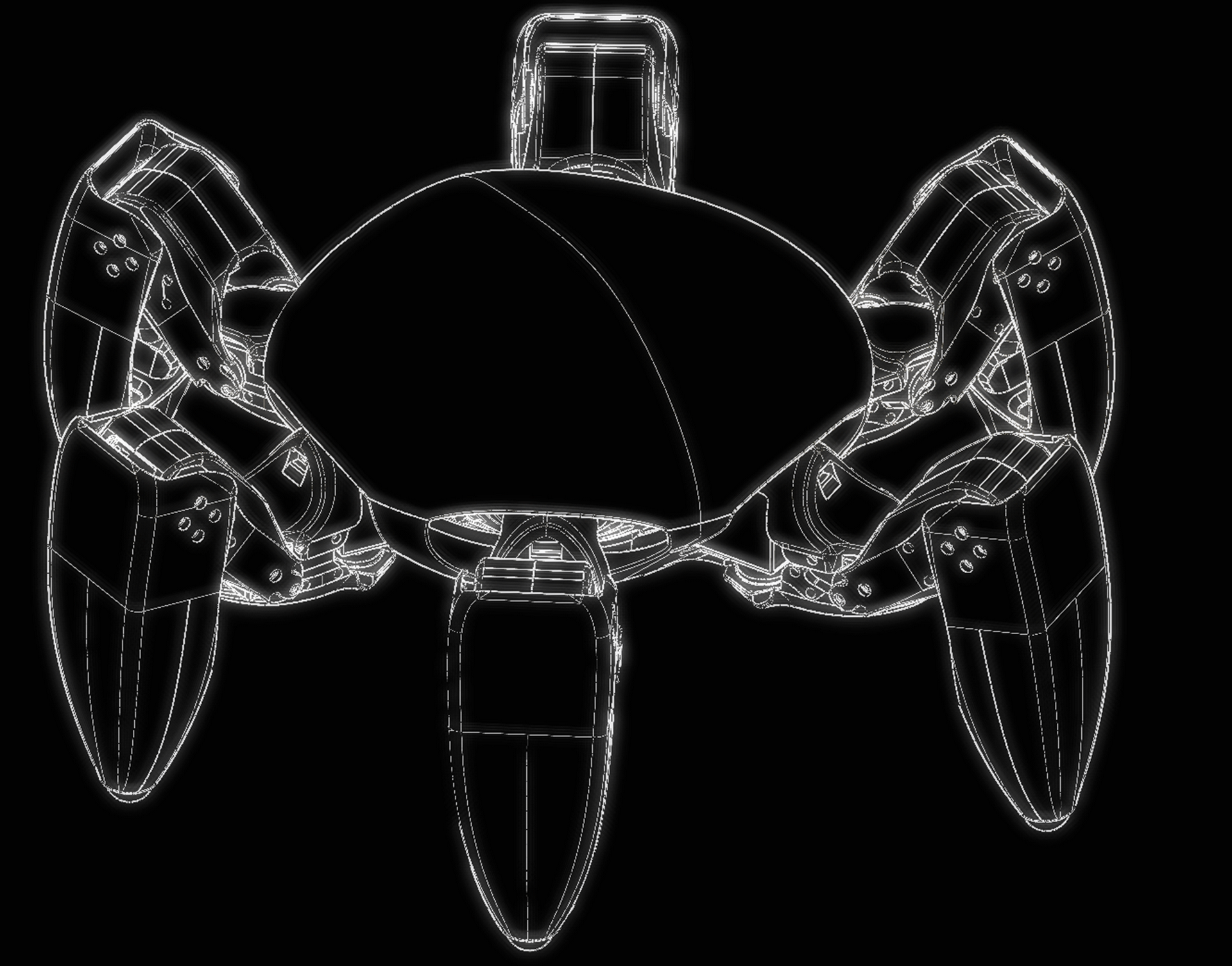
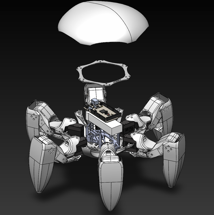
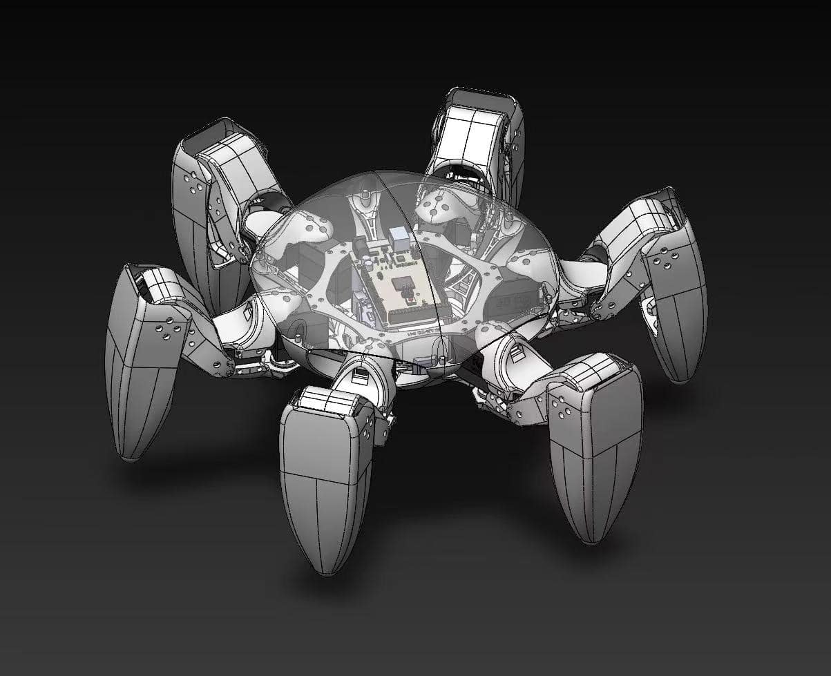
A mechanical platform was modeled in SOLIDWORKS
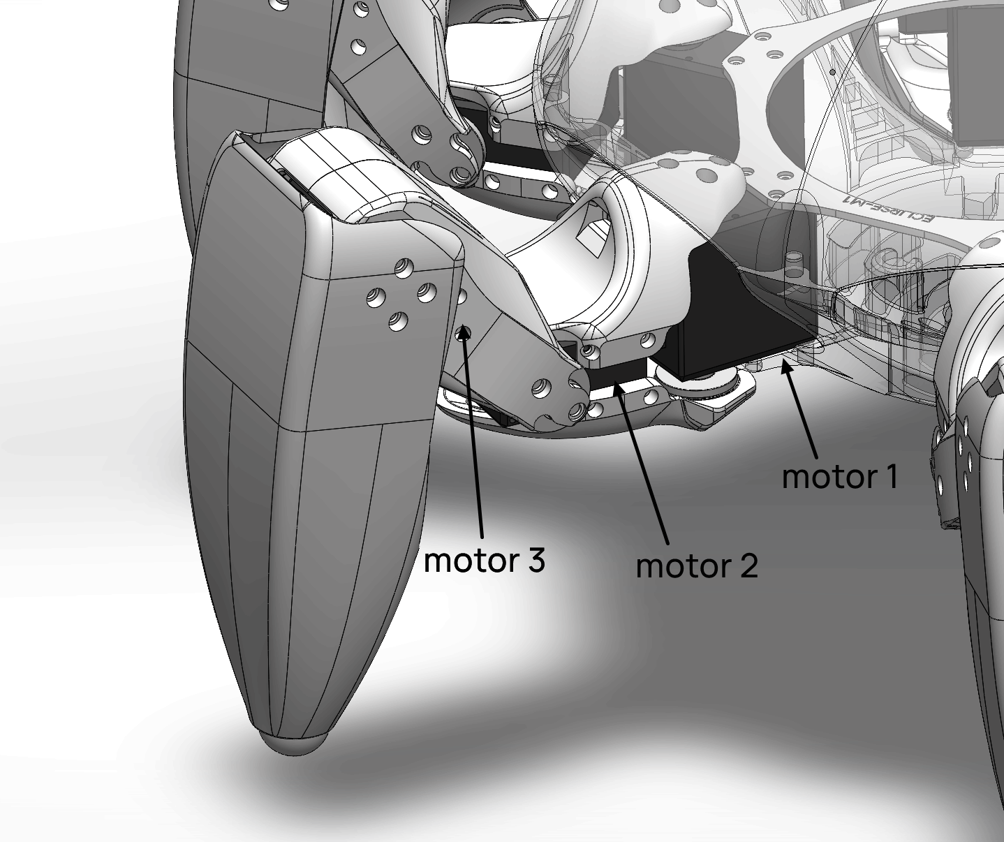
Each leg is outfitted with three joints, with each joint driven by a dedicated DC servo motor, giving the entire robot a total of 18 degrees of freedom.
Motor 1 controls the forward and
backward swing (comparable to a human thigh), while Motors 2 and 3 manage the leg flexion and
extension (comparable to a human calf and ankle).
Kinematic and dynamic simulations were conducted in MATLAB Simscape Multibody. Simulated motion patterns included planar movements, body height adjustments, body swings, and jumping in place.
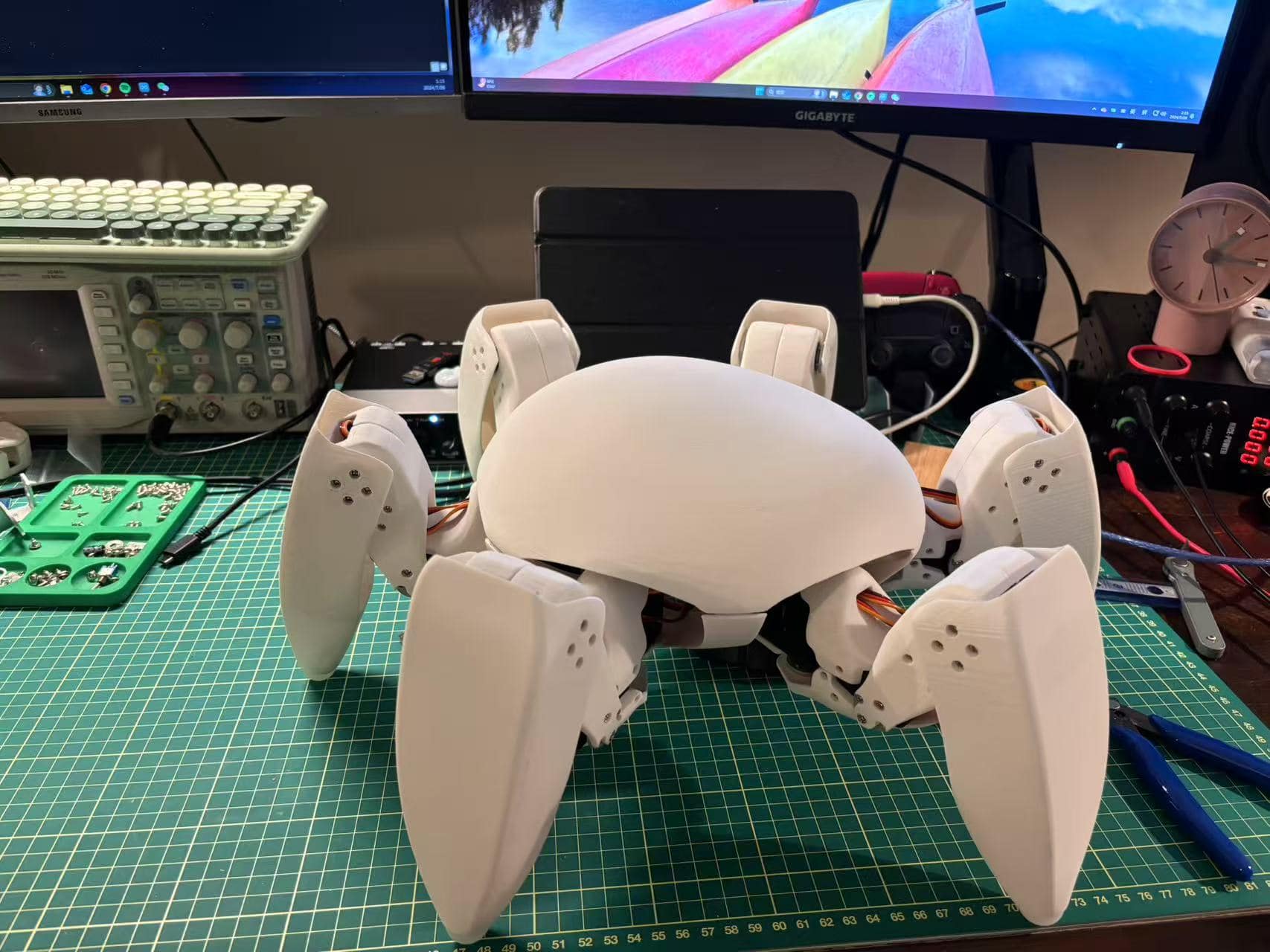
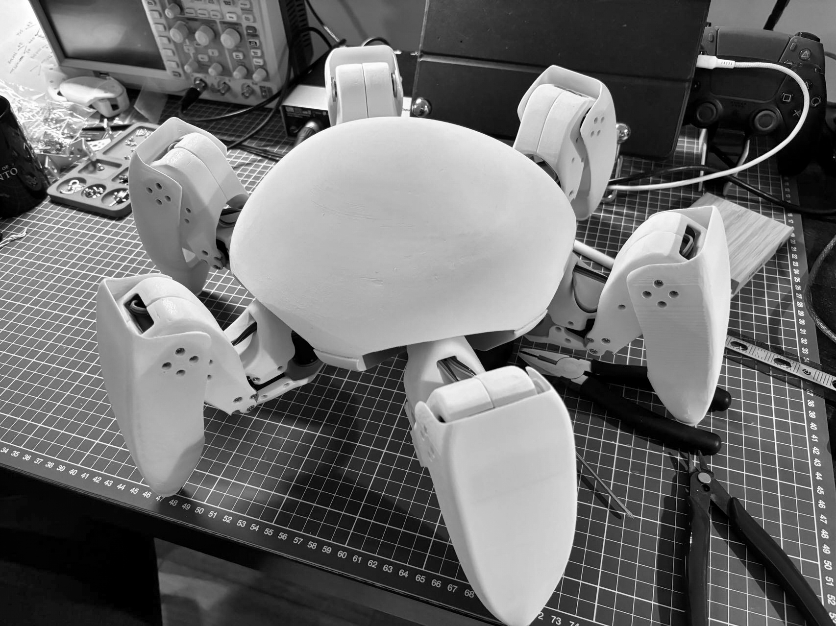
All parts were printed by the FDM 3D printer with PLA.
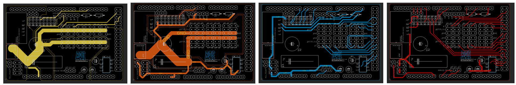
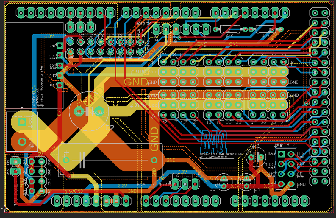
PCB layers (prior copper pour)
(left to right: Vcc layer, GND layer, Signal layer 1, Signal layer 2)
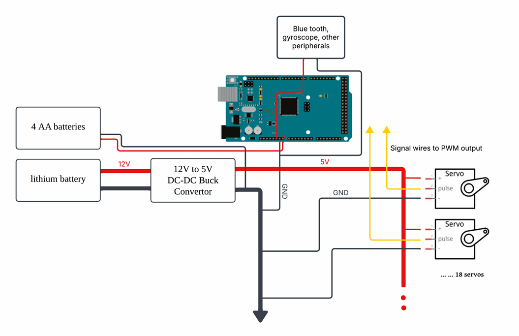
The internal structure of the PCB is divided into a power layer, a GND layer, and two signal layers. The power layer features a main power bus with a trace width of 270 mil, which splits into two
130 mil branches dedicated to powering the 18 motors. At its input, a 0.6F supercapacitor is installed in
parallel with a 1000µF capacitor to mitigate voltage drops that may occur during frequent motor operation.
The GND layer is routed with 270 mil traces to connect the grounds of all components, employing a star
grounding method to minimize potential parasitic effects. The signal layers use trace widths ranging from
14 to 40 mil. Due to the large number of signal traces, the signal routing is split into two layers to avoid
crosstalk. The control signals for the 18 motors are connected to the Arduino Mega’s pins 22 through 45
(with the PCB designed to support up to 24 motors, providing expansion possibilities for the future). The
pins for the Bluetooth and gyroscope modules are also routed on these signal layers.
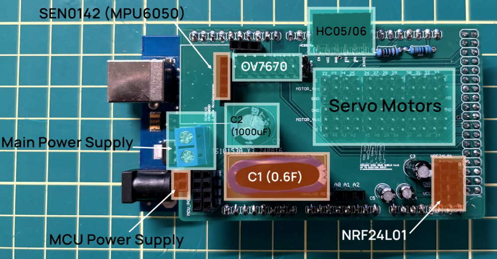
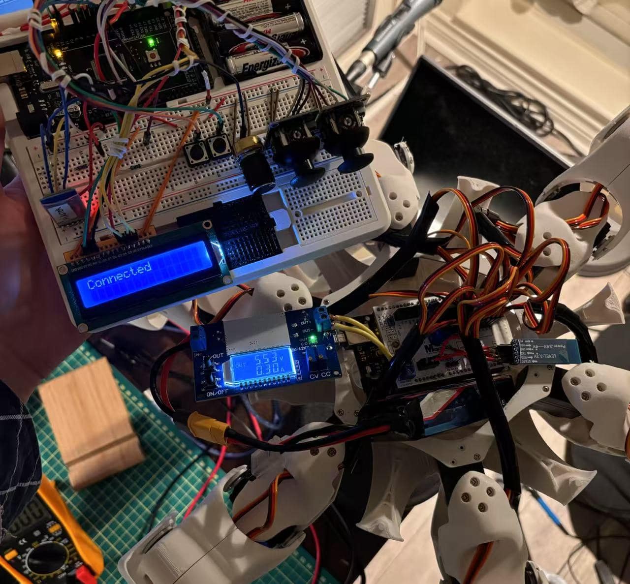
PCB top view
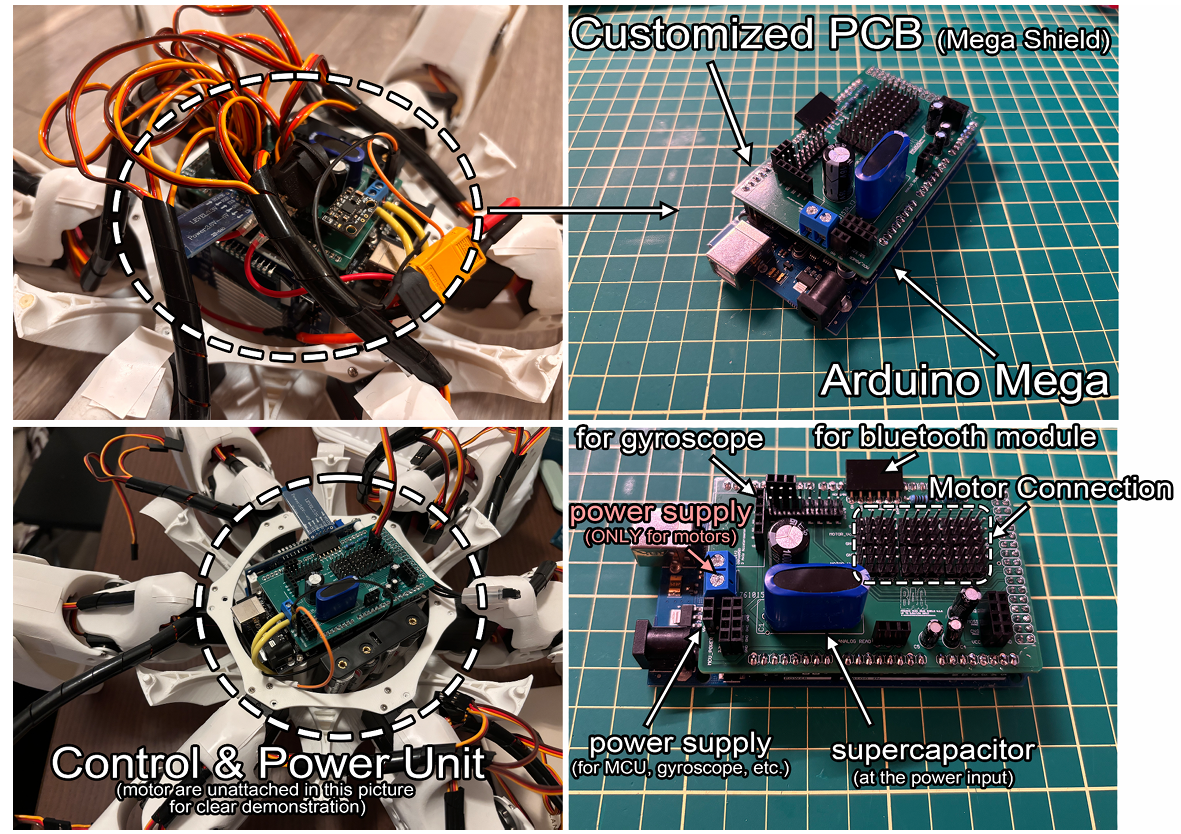
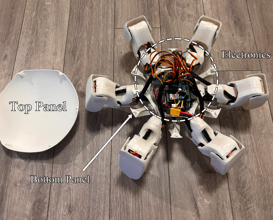
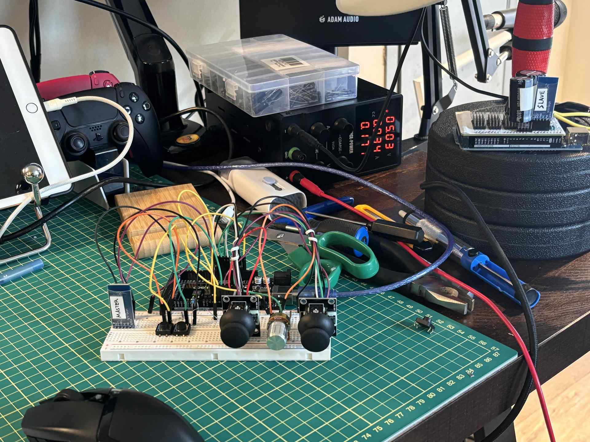
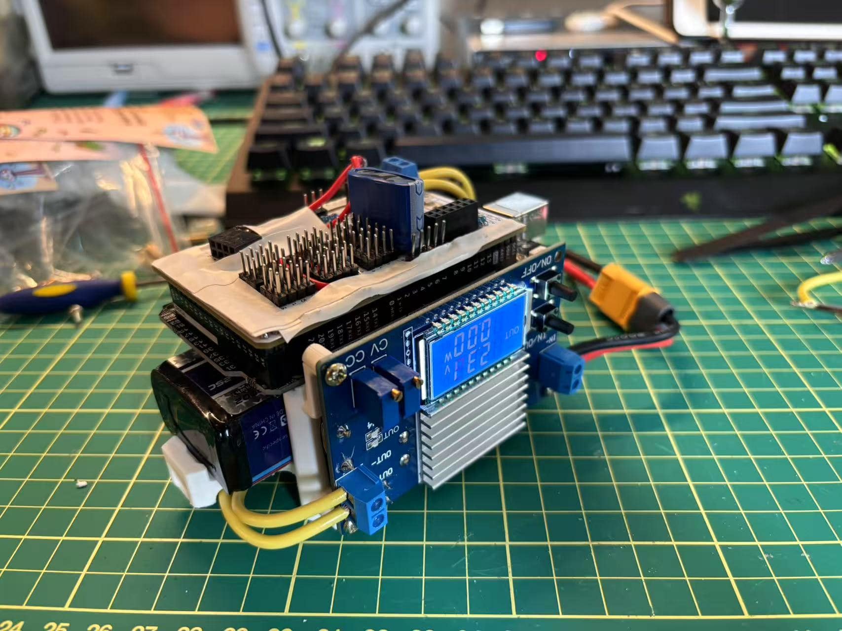
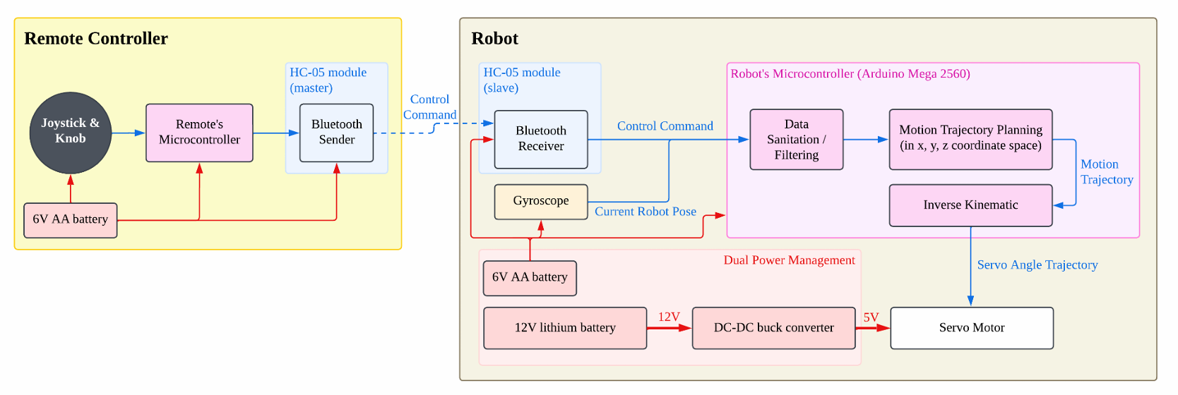
Robot electronics
At each time step, the robot generates the trajectory of the leg-lifting motion (from the point where the leg is lifted to the point where it lands) and transfer this as the inputs into the inverse kinematic equations to determine the angle for each motor. After passing through a Kalman filter, these angles are deployed to each motor.
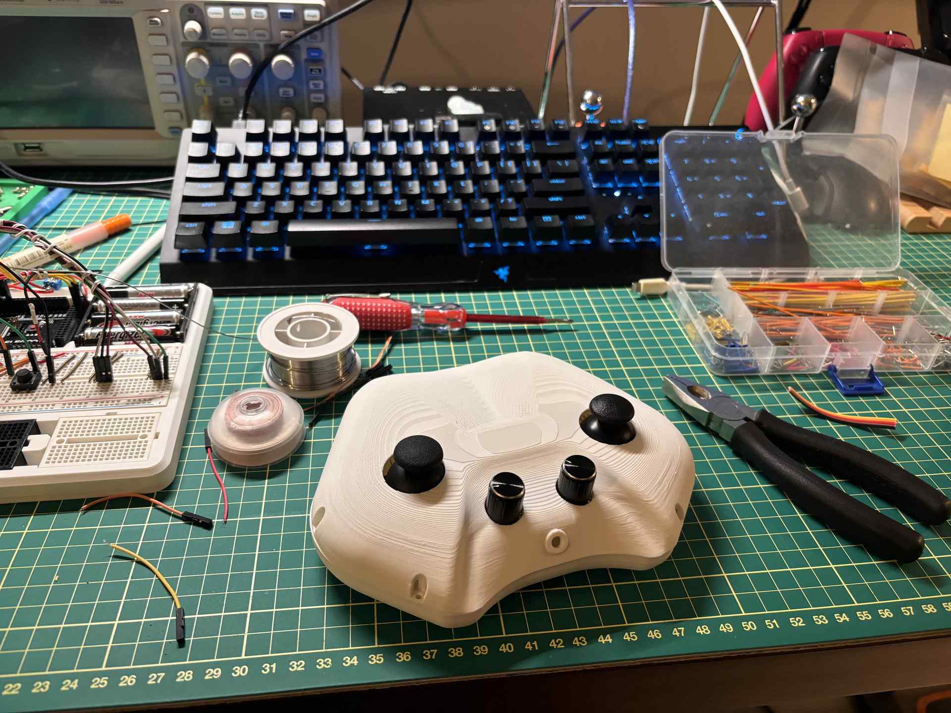
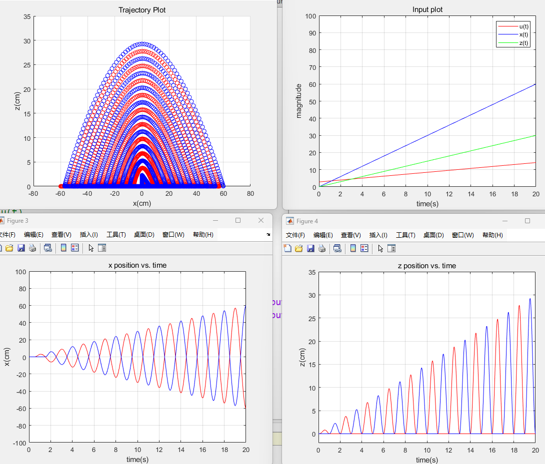
The robot’s walking motion is controlled by a joystick, with the joystick input value denoted asu(t).The following diagram shows the movement trajectories of the robot’s leg end effectors for different u(t) as the input (with x representing the horizontal direction and z representing the vertical direction, under the local reference frame for each leg).
The robot has six legs, which are divided into two groups during walking. Group A includes legs 1, 3, and 5, while Group B includes legs 2, 4, and 6. When Group A is lifted, Group B is on the ground, maintaining a fixed phase offset between the two groups to ensure the robot’s balance. Generated trajectories for Group A (in red) and Group B (in blue) are shown below.
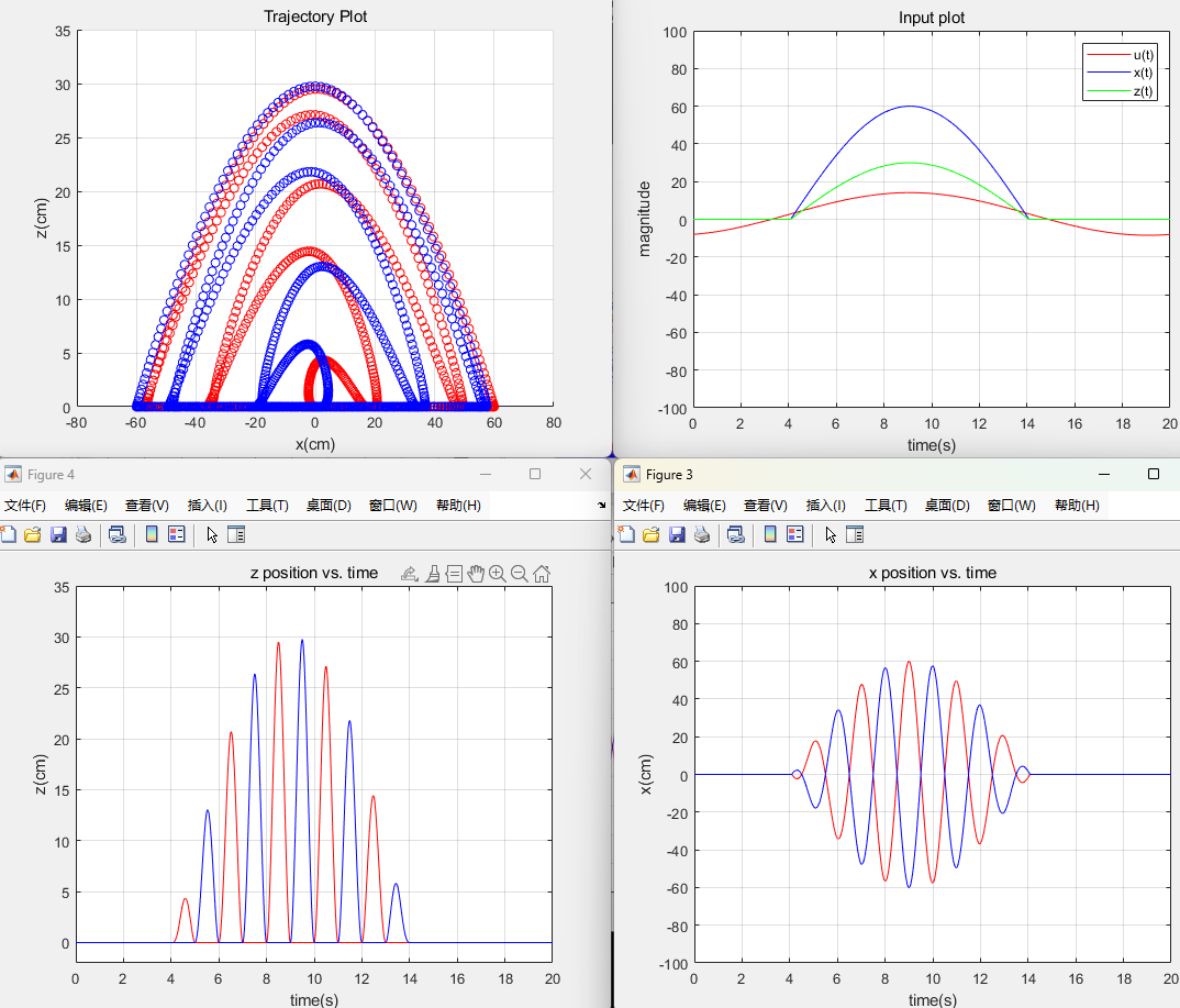
(when u(t) is a sine wave, shown as the red line on the top right figure)
(when u(t) increases linearly with respect to the time, shown as the red line on the top right figure)
The robot is also equipped with a MPU6050 gyroscope module. The MPU6050 IMU provides raw accelerometer data that is used to calculate the robot's roll and pitch angles, thus enables the robot to balance its body during walking on uneven terrain.